
Impact Rollers / Impact Compaction Rollers
What Defines an Impact Roller or Impact Compaction Roller
and What is it's PurposeThe name Impact Roller or Impact Compaction Roller can be misleading in that it implies a rolling cylinder as used in conventional vibrating and static road rollers. Impact rollers are characterised by non-cylindrical multisided geometrical Drum or Module. The number of sides can vary from three to five. The other defining characteristic is that Impact Rollers derive their energy by turning on their corner (major radius) and falling to the flat side (minor radius). There being no motorised form of energy such as in a vibrating roller.
The purpose of an Impact roller or Impact Compaction Roller is to introduce energy to the ground surface in quick succession, around two impacts per second. By doing this in a rolling action at around 10kph large areas can be treated quickly and a large amount of energy applied to an area in a comparatively short period of time.
Impact rollers and Impact Compaction Rollers differ from conventional rollers in their ability to compact material at depth- depth of influence. Conventional vibrating rollers have a depth of influence of around 300mm in cohesive soils whereas Impact rollers have a depth of influence of 700 to 2500 mm in cohesive soils. In non-cohesive materials depth of influence have been recorded at 3 to 4 m.
The economic advantage of using Impact Rollers and Impact Comapction Rollers stems directly from their depth of influence in in situ materials. By way of example: one hectare compacted to a depth of one meter in situ using a medium energy Impact Roller would take 19.2 hours (assuming 20 passes). The same process by conventional excavate and re-compact method would require the following process.
- Excavate and stockpile 10,000m3
- Cart from stock pile and spread 3 lifts of 10,000m2
- Compact 3 lifts of 10,000m2
The depth of influence of an impact roller and Impact Comapction Roller is a product of its energy rating -in Kilojoules. Rollers currently available vary from 12kJ to 30kJ (Potential Energy rating). The higher the energy rating the greater the depth of influence. The number of sides of an Impact Roller has an influence on the energy rating. Since an Impact Roller turns on its major radius and falls to its minor radius, the greater the difference of these radii the greater the lift height. Three sided rollers produce the maximum lift while five sided rollers produce the least lift.
The application of Impact Rollers and Impact Comapction Rollers fall in the following broad categories:
- Bulk earth works. Compacting in 1m lifts at 10kph one machine can compact 18,000 BCM per shift.
- Ground Improvement, uncontrolled fill sites. Compacting to 2-3m depth in situ.
- Induced settlement. The application of a large amount of energy greatly in excess of that imposed in service can bring forward projected settlement.
- Sanitary Landfill. Old landfills can be put to higher land use such as sporting fields and residential areas.
- Problem sites, high foundation costs. With a combination of ground treatment and engineered footing and structures, piling or stone columns and other high cost foundation treatments can be avoided.
Individual manufactures of Impact rollers and Impact Compaction Rollers may make vested interest claims to support their particular design and some go to extraordinary lengths, even presenting such claims as scientific papers. The technology behind Impact Rollers and Impact Compaction Rollers is basic physics, and manufacturers can and should provide prospective users with the basic data to validate claims.
It should be noted that from a Geotechnical perspective that all information is site specific and the transposing of site information from one site to another is not without hazards.
Technical Characteristics
Working device of 6830/6825/6825A impact compactor – impacting drum, is a rolling drum structure of non-circular shape. During roll compacting, potential energy that be reversed when farthest point away drum axial contacts on ground is diverted into kinetic energy at the moment when the nearest point reaches the ground to strike the ground surface, in addition to instant release of hydraulic energy, commonly exert onto the ground to realize high compaction.
While high impact energy is applied on the ground, the counterforce from the ground is sent to drum axles, machine frame, and towing vehicle. Therefore necessary multiply stages of buffering devices are fitted. There are buffering springs at towing pin, damping rubber pad at the rocker limit end, on another end are mounted buffering oil cylinders and accumulator, rubber sleeves mounted between the impact drum and towing frame. Damper isolators between impact drum and its hub and etc. The buffering mechanisms greatly release the shock of the impacting force to the machine frame and towing vehicle.
Hydraulic system of impact compactor is provided with oil from the hydraulic circuit in the towing vehicle, joined by quick couplers with features of safe and rapid operation and easy dismounting.
Actuating lift cylinder to raise up the impact drum away from the ground, in result, entire weight applies on the frame supported with the rubber tyres on the ground. The towing vehicle can draw the compactor for short distance between construction sites without damage to road surface.
NOTES: In operation, motor grader or bulldozer, water spraying vehicle should coordinate with impact compactor for more efficient compaction.
Comparing Compact Rollers
An Impact Roller / Impact Compaction Roller is to provide compaction at depth i.e. Depth of Influence. The depth of influence is directly proportional to the energy generated by an Impact Roller / Impact Compaction Roller. It therefore follows that if a comparison is made of the energy rating of various Impact Rollers / Impact Compaction Rollers an effective indication of performance can be determined.
Over the years manufacturers have made elusive claims for their products and have avoided making any direct comparisons between rollers. They have certainly not shown a willingness to offer their products for independent testing or evaluation.
Gravity is the most significant and active force acting on an Impact Roller / Impact Compaction Roller. The other force is rotational velocity. Since all Impact Rollers / Impact Compaction Rollers operate at similar travel speed of 10kph, by education we can therefore assume that rotational velocity, being a product of travel and speed, is largely consistent for all forms of Impact Rollers / Impact Compaction Rollers. No manufacturer has simply and effectively provided a means of arriving at rotational velocity. One manufacturer of four sided rollers claims a spring energy advantage but does not provide details. This is commented on further in these notes.
Since gravity is the major force the most appropriate expression for calculating energy of an impact roller would seem to be:
E = m.g.h. (E= Energy (KJ), m=mass (t), g=gravity (9.8m/sec/sec ), h=lift height(m).
This being the expression for Potential Energy.
The proponents for rotational velocity as being the major active force suggest the Kinetic Energy expression is the preferred expression:
E = ½ mv2 (e=energy (KJ), m=mass (t), v=velocity (m/sec))The kinetic energy expression relies on velocity which in itself has two limitations. Firstly, the travel speed of all rollers is limited to 10kph by practical factors. Secondly, no rel;iable and effective method of calculating rotational velocity has been provided in the last 20 years, the exception being Dr Clifford’s paper calculating the energy delivered by Impact Roller / Impact Compaction Roller 1995. Dr Clifford refers to “IE” energy as being “potential Kinetic Energy”.
The kinetic energy expression would seem to be more related to calculating the energy of a rifle bullet where velocity at impact is the extreme factor affecting energy.
Using kinetic energy as a comparison between Impact Rollers / Impact Compaction Rollers would seem to be the hard way to do a rather simple task. Put another way it would seem that there are fewer unknowns in assessing potential energy than in assessing kinetic energy. It is also worth noting that due to varying soil conditions at the point of impact it is not possible to know the amount of energy actually transferred to the ground and, regardless of describing energy as potential kinetic energy, all energy is realisable or available subject to ground conditions on an impact to impact basis.
To elaborate on the practical factors concerning speed, (10kph) of an Impact Roller / Impact Compaction Roller as previously mentioned, the practical speed of an Impact Roller / Impact Compaction Roller is in the range of 8 to 11 kph depending upon ground conditions. In excess of 11kph the drum begins to “skip” as the drum revolutions increase with travel speed. The drum tends to act with less impact and eventually will run as a circular wheel given sufficient RPM.We previously referred tp “spring energy advantage” in paragraph 3; the manufacturer of a four sided roller claims a 10 to 20% energy advantage in their Vertical Link compression Spring. However, no details are supplied as to how this is determined. Operators of these four sided Impact Rollers / Impact Compaction Rollers over a period of years make the comment that once the roller is at operating speed the Vertical Link compression springs remain compressed under the inertia force of maintaining the roller operating travel speed. It would seem that the springs release their energy at around 6kph but not at the 10 – 12 kph recommended operating speed.
Based on the above anecdotal evidence and the the absence of facts to the contrary it would seem that the claimed spring advantage is unlikely to realised and/or is only very minimal in its effect.
The following table contains information taken from published data by roller suppliers and is believed to be correct at time of publication. Such information is marked (p).
Impact Roller / Impact Compaction Roller
Mass (p)
(M)Lift (p)
(h)Potential Energy
Kinetic Energy
Number of sides (p)
Propulsion (p)
Remoplains
16.2t
0.360m
37kj
169kj
3
Drawn
Landpac
11.0t
.0230m
25kj
115kj
3
Self Propelled
Broons
7.9t
0.150m
12kj
55kj
4
Drawn
Broons
11.5t
.0150m
17kj
78kj
4
Drawn
Landpac
10.5t
0.150m
15kj
69kj
5
Self Propelled
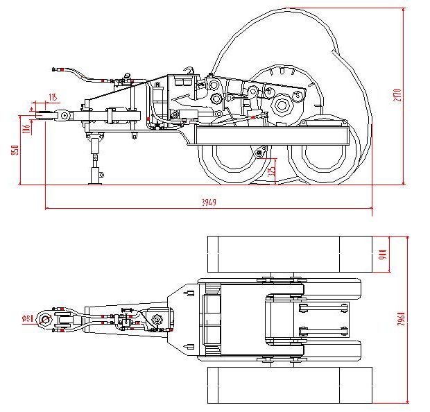
Square 63214C Impactor
The square steel module has a mass of approximately 8T. It is drawn in its 6T frame. Impact rolling is suitable for a wide variety of materials and is less dependent on the materials moisture content to achieve the desired improvement. The impact rollers ability to equalise the density gradient across a site, developing a more uniform soil “raft” lends itself to a wide variety of applications.
Square Impactor 63214CMass: 13980kg Width: 2626mm Length: 4635mm Height: 1750mm Drum Width: 1300mm Maximum Impact Energy: 32kj Depth of Compaction: 0.5 – 2.5m Compaction Frequency: 75-140 hit/min Operating Speed: 8-15km/h Lift: 220mm Breaking Force: 206820kpa
RANGE OF APPLICATIONS
Pavement Reconstruction.
A significant innovation for the reconstruction of rural roads in Australia has been realised through the use of the impact roller. The impact roller has been used on a regular basis by a number of local councils on rural roads where there are no sewers or other services below the pavement, while more caution is required in metropolitan areas due to the myriad of shallow underground services.
One of the biggest problems for rural roads is localised or more widespread failure due to poor subgrade conditions. The major benefit of the impact roller is that the subgrade can be improved from the surface, without the need to remove any material. Sealed pavements and even concrete stabilised base courses are broken up under impact rolling, leaving a material suitable as the new sub-base. Sufficient settlement is usually induced by impact rolling, so that after shaping and conventional rolling, a new base course and wearing course can be laid without further earthworks.Agricultural Sector
In the Australian agricultural sector, impact rolling has been utilised since the early 1990’s to address problems with leakage from water storages and channels for the cotton and rice industries. More recently, impact rolling has been successfully deployed in the construction of pads for beef cattle feedlots, where environmental constraints require properly engineered facilities.
The ground improvement generated by the “square” impact roller in the agricultural sector offers significant environmental benefits. Water loss through permeation from water storages and channel banks is reduced, which reduces the impact on groundwater and soil salinisation. The reduction in irrigation water consumption improves the environmental sustainability of high water-use crops.
Brownfield Sites
The widest application of the “square” impact roller in Australian metropolitan areas relates to the redevelopment of former industrial sites. Sometimes these “brownfield” sites are re-used for industrial purposes, but often they are developed for residential use, which generally requires more remediation due to a more sensitive end use.
In common to most existing industrial sites, the land has been filled. Generally, this fill has been required to provide a level base for slabs and pavements, but often more marginal land, zoned for industrial use, has had deeper amounts of fill placed over sometimes poor, soft or weaker soils. Over decades of use, fill materials have become contaminated and waste materials have been buried on older industrial sites. The challenge for the remediation team is to find a solution that is environmentally sound but also realising a cost-benefit to the developer.
Impact rolling provides an alternative to re-engineering existing fill. Materials that are environmentally suited to retention on site, but that may otherwise need to be taken off site if excavated, can often respond to impact rolling to produce suitable subgrade conditions.
Mine Waste Tips
The mining sector was an early advocate of impact rolling to reduce the incidence of spontaneous combustion in coal stockpiles, a use that still continues in South Africa today. In Australia, the “square” impact roller has been utilised on numerous mine sites to improve mine haul roads, in the construction of tailings, dams and to compact the capping over waste rock cells.
The most recent work undertaken by the “square” impact roller at a mine site is, however, a non-engineering application. On the hard rock open cut gold mines, spoil is carted by 300t haul trucks and end-tipped to form large waste rock tips. The trucks drive up onto the tip head and then turn through 180̊ and reverse to the edge to dump the load. During turning, the truck tyres are particularly prone to damage from protruding hard sharp rocks. The cost of truck tyres is the largest single cost to the mining operation of the largest open cut gold mine in Kalgoorlie, Western Australia.
Impact rolling on the tip head to “rubblize” the rock has the effect of breaking down larger sharper rocks, with an associated reduction in abnormal tyre wear. The “square” impact roller module is specifically modified for such mining applications.
Landfills
The provision of adequate landfill void space in and around existing and developing cities is an ever-growing problem. As a general rule, landfill operators utilise a unit that combines compaction and dozing, which compacts while it traverses and spreads the fill material and can also spread soil cover. While this approach generally serves the purposes for which it is deployed, the extent of future gross and differential settlement that occurs in refuse tips is still substantial. When such sites are later turned over to, say, recreational use, problems frequently arise with differential settlement and associated risks to site users.
The “square” impact roller has been utilised on numerous landfills, particularly in Victoria, Queensland and Western Australia, as well as other Australian states and overseas. Due to the extremely variable and heterogeneous nature of waste, and difficulties associated with testing such materials, there is a limited amount of quantified output from impact roller work on landfills, most users relying on observational techniques to substantiate the impact roller’s effect.
Two locations were selected from the data set to illustrate the variable response that can be expected on such sites. The landfill had a soil capping of approximately 1m thickness overlying the waste material and the trial alignment was subjected to 90 passes. Modest settlements of 200mm to 250mm were recorded after approximately 40 passes where the fill was shallowest (less than 3m thick). However, where the fill was deeper than 5m, a maximum settlement of approximately 700mm was recorded after 90 passes. The use of the impact roller on landfills at various times during the placement of the fill is likely to provide additional landfill capacity during the filling process. Initial cost estimates indicate that this is an attractive scenario, particularly as the cost of waste disposal continues to rise.Land Reclamation
Land reclamation projects generally take the form of creating new land at the edge of a water body or raising land that is at or close to the water table or sea level. Frequently, the fill material is sand that is dredged from the sea or river floor, usually placed hydraulically into or onto the area being reclaimed. The “square” impact roller has been used on many such projects to produce a soil “raft” of significant thickness to reduce differential settlements and accommodate infrastructure. This has been undertaken in most Australian states, in the United Kingdom, Hong Kong and the Netherlands.
Test Methods for Monitoring and Validation
Many different test methods are utilised to verify the effects of impact rolling, varying dramatically from site to site and project to project. Some projects, in fact, include no quantitative testing, relying on anecdotal and observational evidence. It is considered that this variation is generally attributed to a combination of the client’s, designer’s and/or geotechnical engineer’s preferences and experience with impact rolling, the readily available test equipment budget constraints, the site’s location and/or particular site conditions.
Send mail to support@lbswebsolutions.com.au with questions or comments about this web site.